
Water intake end-of-pipe fish screens
This interim standard provides Fisheries and Oceans Canada’s (DFO) national guidance on the implementation of end-of-pipe fish screens occurring within freshwater (includes rivers, streams, lakes, and ponds) and marine environments.
On this page
1.0 About this standard
A standard specifies how to implement a specific mitigation measures to achieve its objective and maximize its effectiveness. This standard provides national guidance from Fisheries and Oceans Canada (DFO) on how to implement the following mitigation measure:
- Screen water intake pipes throughout the course of water intake operation
This interim standard is intended for use in the implementation of end-of-pipe fish screens occurring within freshwater (includes rivers, streams, lakes, and ponds) and marine environments.
By following this standard, project proponents can reduce the risk of harmful impacts to fish to an acceptable level.
Fish screens are required when water intakes are deployed to reduce the risk of harmful impacts to fish from impingement and entrainment during water withdrawal activities. This standard provides guidance to proponents on specific criteria and guidelines associated with fish screens, including deployment, design specifications, and the maintenance of the screen during use. Fish screens may be required to support works, undertakings and activities such as the construction of new infrastructure or to support maintenance, repair or removal activities associated with existing in-water infrastructure. Examples of projects that this standard applies to include:
- in-water construction projects that require a temporary dry working environment (consult the Standard: In-water site isolation if your project requires the isolation of an in-water site)
- water pumping such as cast-in-place concrete works associated with water intake and outfall structures, boat ramp construction, bridge, culvert, pipeline and telecommunication line crossings, shoreline or in-water dredging, or excavation activities
- water collection for irrigation, dust suppression, and water supply
- mining exploration and mining (for example, drilling, milling activities)
- oil and gas extraction (for example, fracking)
2.0 User guide
Standards are one of a suite of tools used by the Fish and Fish Habitat Protection Program (FFHPP) to manage the risk of harmful impacts to fish and fish habitat from projects carried out in or near water. They create efficiencies in the regulatory process by standardizing requirements for certain types of common projects.
Standards are not considered stand-alone documents. The conditions under which they can be applied, other applicable management measures (for example, carry out the project in accordance with timing windows), and any engagement or consultation requirements are dictated by the instrument within which the standard is referenced (for example, Fisheries Act Authorization).
Project proponents can indicate their intention to follow one or more Fisheries and Oceans Canada (DFO) standards in their request for review or when submitting an application for authorization. Submissions should indicate specific sections of the standards that apply to the proposed project, and include any additional site-specific management measures related to the method used.
This standard is intended to be used for all water intakes deployed in:
- freshwater watercourses (for example, rivers and streams)
- freshwater water bodies (for example, lakes and ponds)
- marine environments
- This standard does not address the risk of harmful impacts to fish and fish habitat from the physical installation of water intake pipes or the volume of the water withdrawal. It is recommended that fish screens and water intakes be installed in areas that avoid high quality habitat features (for example, heavily vegetated areas and/or woody debris and similar structures in freshwater habitats; reefs, seagrass beds, and salt marshes in marine environments).
We acknowledge the methods specified in this standard may not be applicable to large water intakes or high withdrawal rates.
If you are uncertain about what methods should be applied based on site-specific conditions, it is recommended that you consult an expert with an appropriate professional designation. A qualified environmental professional (QEP) will determine the best method(s) based on site-specific conditions.
Standards do not remove nor replace the obligation to comply with all applicable statutory and regulatory requirements of the Fisheries Act, the Species at Risk Act, or other federal, provincial, territorial or municipal legislation and policy including guidance regarding species and habitats managed by these jurisdictions.
Up-to-date information on DFO standards can be found on the Projects near water website.
3.0 Methods
This water intake end-of-pipe fish screens standard includes guidance related to fish screen design criteria, screen installation for water in-take pipe(s), and the cleaning, maintenance and monitoring of the fish screens. Fish screens must be deployed whenever water withdrawal activities occur in fish-bearing waters, and there is potential for entrainment of fish.
Key baseline information on the aquatic environment and the fish community is to be used to inform the required screen design (for example, effective screen area) and water velocities to protect fish. This is applied by considering the poorest fish swim performance group in the watercourse or water body. In the absence of any fish community data, the design should assume that the most limiting swim performance group (for example, anguilliform species) and life stages (for example, early life stages of fish) are present.
Criteria including approach velocity, sweeping velocity, screen/slot size, screen porosity (open screen area), effective screen area, and screen material are considered when designing a fish screen. Please refer to Table C-1 which summarizes these criteria.
3.1 Water velocity
3.1.1 Approach velocity
- Use the End-of-Pipe Screen Size Tool to determine the effective screen area for your project.
- Calculate approach velocity by dividing the water intake flow rate by the effective screen area.
- Implement a design approach velocity according to available fish community and habitat data using the Swim Performance Online Tool (SPOT).
- Implement a maximum design approach velocity of 0.055 m/s for water bodies where fish community or habitat data are not available.
- Implement a design approach velocity of up to 0.12 m/s if the ambient flow is at least twice the design approach velocity.
- Ensure approach velocity does not exceed the values set for each species.
3.1.2 Sweeping velocity
- Consider sweeping velocity when water intakes are deployed in areas with flowing waters.
- Ensure that characterization of sweeping velocity is supported by baseline streamflow and velocity data.
- Modify water intake angle and screen face angle when ambient flow is measurably greater than the approach velocity.
- Angle the sweeping velocity parallel to the screen face with a maximum of 45 degrees relative to the watercourse flow.
- Adhere to sweeping criterion unless there is limited water flow in watercourses and water bodies.
3.2 Screen area
3.2.1 Effective screen area
- Calculate the minimum effective screen area required using the design approach velocity and the quantity of water diverted.
- Ensure the minimum effective screen area equals the quantity of water diverted divided by the design approach.
- Use a maximum slot or opening size of 2.54 mm if there is no presence of eels and small-bodied species-at-risk (< 25 mm fork length).
- Use a maximum slot or opening size of 1 mm in the presence of eels and small-bodied species-at-risk (< 25 mm fork length).
- Ensure a minimum of 50% of the screen area is open.
3.2.2 Screen material
- Use proven or common manufacturer material including welded wedge wire screen, #8 mesh consisting of stainless steel or durable reinforced plastic (See figure 1).
- Ensure that there are no protrusions on the screen surface or supports that could injure fish.
- Use screen material that is resistant to corrosion and UV light.
- Use copper nickel (CuNi) alloys where biofouling is a concern and an active cleaning system is not present.
3.2.3 Screen shape
- Use a manifold on designs where the flow would be uneven across the surface of the screen.
- Position the manifold at an equal distance from the outer screen.
- Cap the manifold at the end with solid materials.
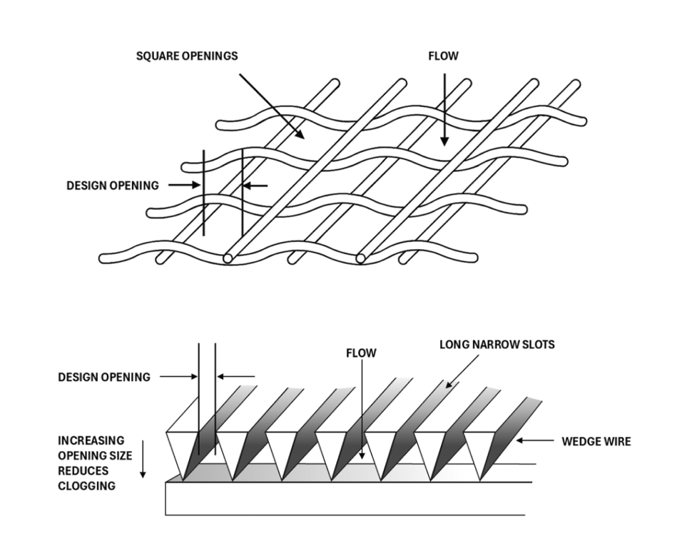
Figure 1: Drawing showing the profile of woven wire mesh and drawing showing the profile of the wedge wire screen with features pointed out: design opening, flow, long narrow slots, wedge wire, increasing opening size reduces clogging. The design opening should not exceed 2.54 millimeters (DFO 1995).
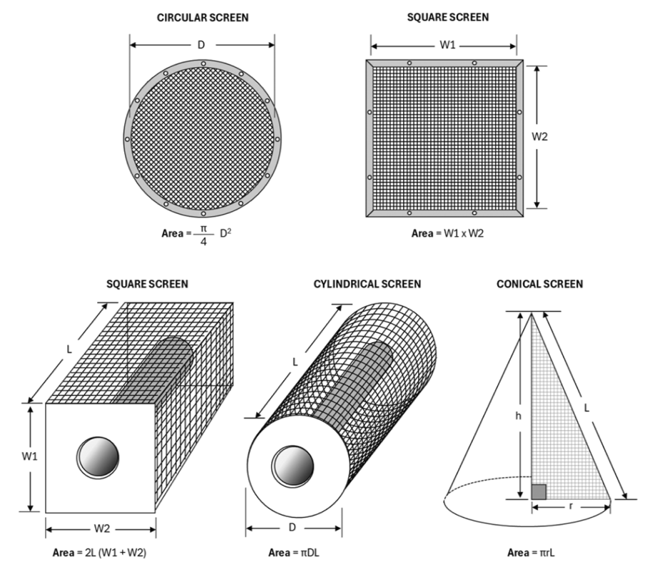
Figure 2: Drawing showing the common screen shapes and effective screen area formula. Note: for semi-hemispherical or half barrel screens adopt half the area for a cylindrical screen (DFO 1995).
3.3 Fish screen installation
The installation and positioning of fish screens in aquatic environments must follow certain criteria to ensure maximum effectiveness in protecting fish.
- Use low profile screens (for example, half barrel or cone shaped) in shallow conditions.
- Install a velocity cap for offshore water intakes to convert vertical flow to horizontal flow at the water intake entrance to mitigate fish entrainment.
- Maintain the minimum effective screen area throughout the course of the project.
- Refer to manufacturers specifications for the type of screen being deployed.
- Account for ice formation with regards to fish screen positioning if the water intake remains operational during the winter.
- Ensure that there is no build-up of ice on the fish screen or that the fish screen becomes completely frozen.
- Ensure all openings for guides and seals are smaller than the opening width of the screen material (2.54 mm) so fish cannot pass through.
- Prevent sagging or collapsing of the screen panel by ensuring enough structural support.
- Account for the areas blocked by supports while meeting the effective screen area design.
- Protect large screens with trash racks fabricated of bar (150 mm spacing is typical) or grating in areas where there is debris loading (for example, woody material, leaves or algae mats).
- Screen placement in watercourses.
- Position fish screen:
- parallel to the flow and bank line in flowing water (for example, watercourses or tidal areas) if feasible, or
- at a maximum angle of 45 degrees relative to the watercourse or tidal flow to optimize the sweeping velocity along the face of the fish screen when parallel to the flow and bank line if the above is not feasible.
- Position fish screen:
- For marine environment:
- install fish screens in marine environments where there is a flow or current to enhance sweeping velocity.
- account for seasonal variations in flow and tidal conditions during fish screen installation as only the submerged part of the screen area contributes to the effective screen area.
3.4 Inspections, cleaning, and maintenance
When fish screens are deployed, they must be inspected and maintained to ensure proper function.
- Develop and implement an inspection plan for the fish screen throughout the course of water intake operation.
- Adapt inspection schedules to consider changes in fish life cycle stages and environmental conditions throughout the course of water intake operation.
- Check the approach velocity directly in front of the screen throughout the course of water intake operation to ensure it does not exceed the designed approach velocity at any location.
- Inspect fish screens daily throughout the course of water intake operation.
- Repair and replace cleaning apparatuses, seals and screens, as needed, throughout the course of water intake operation.
- Record inspection logs.
- Record any observation of death of fish.
- Record impingement, sweeping velocity, and approach velocity data daily when watercourse flow is noticeably reduced, and approach velocity is not protective to fish.
- Record the fish screen's susceptibility of biofouling.
- Record changes to environmental conditions (for example, changes in watercourse flow, drought events) since its installation.
- Record maintenance or activities applied to maintain screen functions as per design criteria.
- Visually inspect the fish screen throughout the water withdrawal period.
- Ensure complete submergence of effective screen area.
- Ensure 100% screen porosity.
- Ensure that there are no signs of impingement.
- Confirm design approach velocities are being maintained.
- Reposition the water intake and fish screen to ensure approach velocities are appropriate as required.
| Criteria | Criterion |
|---|---|
|
Design approach velocity |
The design approach velocity based on the minimum sustained swimming speed of fish species present. The End-of-Pipe Screen Size Tool is used to determine the effective screen area based on the fish species present. Where fish community data or fish habitat data are lacking (meaning, where risks to fish are unknown), the maximum approach velocity is 0.035 m/s for waterbodies. Higher approach velocities can be considered where the probability of encountering small juvenile fish and/or anguilliform species is negligible. If no fish community data is available, the maximum approach velocity is 0.035 m/s for waterbodies with still waters where sweeping velocity considerations do not apply or 50% of sweeping velocity up to a maximum of 0.12 m/s for watercourses where sweeping velocity exceeds approach velocity. Characterization of sweeping velocity in these cases must be supported by baseline streamflow and velocity data. Where sufficient baseline flow data is available for the location of the water intake screen installation in a watercourse or tidal area, designs can consider a design approach velocity above 0.035 m/s assuming the ambient flow velocity and associated sweeping velocity exceeds the design approach velocity by a factor of 2, up to a maximum approach velocity of 0.12 m/s. For example if the sweeping velocity was 0.24 m/s or more, an approach velocity up to 0.12 m/s may be permitted. |
|
Approach velocity |
The approach velocity is calculated as the water intake flow rate divided by the effective screen area. The approach velocity should not exceed the design approach velocity. |
|
Sweeping velocity |
The sweeping velocity is the ambient water velocity parallel and adjacent to the face of the screen. Characterization of sweeping velocity should be supported by baseline streamflow and velocity data. Modifications to the design approach velocity are applied when the velocity of ambient flow is measurably greater than the approach velocity; ideal angle of sweeping velocity is parallel to the screen face, and maximum of 45 degrees relative to the watercourse flow. Sweeping velocity should be considered when water intakes are deployed in areas with flowing waters, which can include rivers, streams, channels, and tidal zones in marine environments. Due to limited water flow in waterbodies, such as lakes, ponds, and reservoirs, the sweeping velocity criterion typically does not apply. |
|
Effective screen area |
The design approach velocity and the quantity of water diverted is used to calculate the minimum effective screen area required. Minimum effective screen area (m2)= quantity of water diverted (m3/s)/(design approach velocity (m/s) Note: Only the submerged area of the screen is considered. |
|
Opening / slot size |
|
|
Screen porosity |
Ensure a minimum of 50% of the screen area is open |
|
Screen material (figure 1) |
|
|
Screen shape |
|
4.0 Glossary
- Ambient flow
- The water velocity measured without the installation or operation of the water intake and fish screen.
- Approach velocity
- The water velocity measured directly in front of the intake screen.
- Design opening
- The narrowest dimension of any opening on the screen, regardless of opening shape.
- Effective screen area
- The area of the open spaces available for the free flow of water, including screen material but excluding major support structures.
- Entrainment
- Occurs when a fish is drawn into a water intake and cannot escape.
- Fish
- As defined in the Fisheries Act, fish includes:
- parts of fish
- shellfish, crustaceans, marine animals and any parts of shellfish, crustaceans or marine animals
- the eggs, sperm, spawn, larvae, spat and juvenile stages of fish, shellfish, crustaceans and marine animals
- Fork length
- The straight-line distance measured from the tip of the nose to the fork of the tail of a fish.
- Impingement
- Occurs when an entrapped fish is held in contact with the intake screen and is unable to free itself.
- Marine environment
- Comprises all ocean, coastal waters, and estuaries, including intertidal zones and salt water marshes, and extending, in the case of watercourses, up to the freshwater limit.
- Qualified environmental professional (QEP)
- A person experienced in identifying and analyzing risks to fish and fish habitat generated from various works, undertakings or activities conducted in or near water, and implementing management measures to avoid and mitigate those risks. They possess a post-secondary degree or diploma in biological, geophysical or environmental sciences and are referred to as:
- applied scientists
- aquatic biologists
- environmental consultants
- fisheries biologists
- fisheries technicians
- fluvial geomorphologists
- natural resource consultants
- Sweeping velocity
- The ambient water velocity parallel and adjacent to the face of the screen.
- Water intake flow rate
- The amount of water withdrawn over time.
- Date modified: